How To Load Program For At89c51

Electronics Projects – The projects which are having more demand in engineering level and especially very useful for ECE and EEE students. We are all well known that we cannot imagine our life without electricity even for single day as it became a part in our life. So, it is very important and beneficial to us if we learn some basic things about electronics. This electronics concept deals with various small and large circuits which may include concepts like diodes, batteries, resistors, integrated circuits, etc. These concepts are very interesting to learn also. As day by day its importance growing at rapid rate.
For this project you will need the following: COMPONENTS: 1. An Arduino (any kind will do) 2. A dual-7 segmant display or 2 seperate 7 segment displays. 2 Resistors (the values depend on your display) 4.
About 50cm of non-stranded wire TOOLS: 1. A soldering iron and solder.
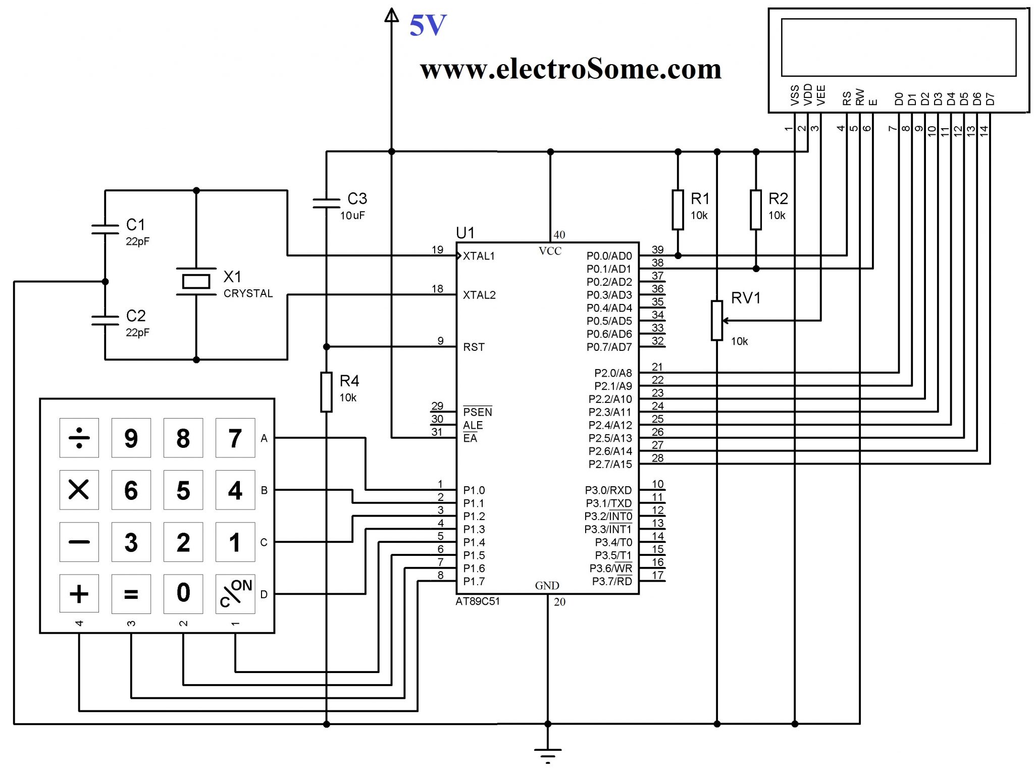
Top and best electronics projects ideas list for final year ECE and EEE students along with all sources like circuit diagram, code, abstract & output video. The Atmel AT89C51 is an 8051-based Fullly Static 24MHz CMOS controller with 32 I/O Lines, 2 Timers/Counters, 6 Interrupts/2 Priority Levels, UART, Three-Level Program Memory Lock, 4K Bytes Flash Memory, 128 Bytes On-chip RAM.

(My display was SMD so i had to solder wires to it for connection) 2. A fume extractor.
(I really reccomend buying or making one as they are very helpful to you) 3. A wire stripper, or you could just use scissors Step 2: What Is Multiplexing? Multiplexing is when you control lots of LEDs with a few IO pins.
Avast Secureline Vpn License Key Download. It is based on having to or more 7 segment displays and connecting them together, an example of what they would display is 00, 11, 22, 33, 44, 55, 66, 77, 88, 99. But what we do in this case is control each GND (-) induvidualy which turns it into a multiplexed display. We will switch displays every 0.5ms which gives us control of each display.
It is usefull when you are building a project with lots of components and are short of IO pins. In this example, we will be controlling 2 7 segment displays with 9 IO pins. If we don't use multiplexing, we will need 14 IO pins to control the whole thing. Step 3: The Build. This project is quite complicated so you will need basic electronic skills.
First you will have to solder wires on the back to make the multiplexing circuit. This can be done on a breadboard if your display is not SMD. How To Install No Hope Mod World In Conflict Cheats there. Secondy, solder on jumper wires to plug the display into the breadboard.
Thirdly, connect wires from the breadboard to the Arduino in this sequence: Segment A: pin 7 Segment B: pin 8 Segment C: pin 4 Segment D: pin 3 Segment E: pin 2 Segment F: pin 6 Segment G: pin 5 Gnd1 via resistor: pin 11 Gnd2 via resistor: pin 9 Step 4: The Programming!!! THE CODE TIME!!! This is my favourite part of any project, because i know it is almost complete! I have wrote 2 programs: one that counts down from 20, and another that scrolls the message'Arduino' across the displays. I will explain some of it in the code, just so you can understand it a bit better.
In the beginning, it initialises all the pins, and sets a few variables. In the Void Setup, it sets up all the pins as outputs. It also contains lots of FOR LOOPS, which are used when the LEDs are switched. In the Void Loop, it sets pin 13 high and fades the 2 gnd pins on and off, which displays a pulsing 00. Improvement hint: It looks like you used something like two 170 ohm resistors.
Assuming this, you receive a (constant) current of about 17mA for one digit (@5V source and 2V forward voltage per LED). This current will be divided into 1 to 7 segments, depending on how many of them are turned on. That's why the number 1 illuminates much brighter than a 8 in your video. That's a really bad design for a 7-segment. Use 680 ohm resistor per segment (!) instead to receive equal brightness. You will get less than 5mA per segment, one µC digital pin can sink 40mA max.
More brightness can be achieved with external open-collector circuitry and smaller resistors.